
How I Made A PCB - W220 Project

I was thinking about how I was going to connect everything I needed to my ESP32 development board for my power automation in my W220 Project. I prototyped with small jumper wires, however, I realized it was unfeasible to use this strategy for the final build, as the wires are messy and can be easily disconnected in a vibration prone environment, like a car.
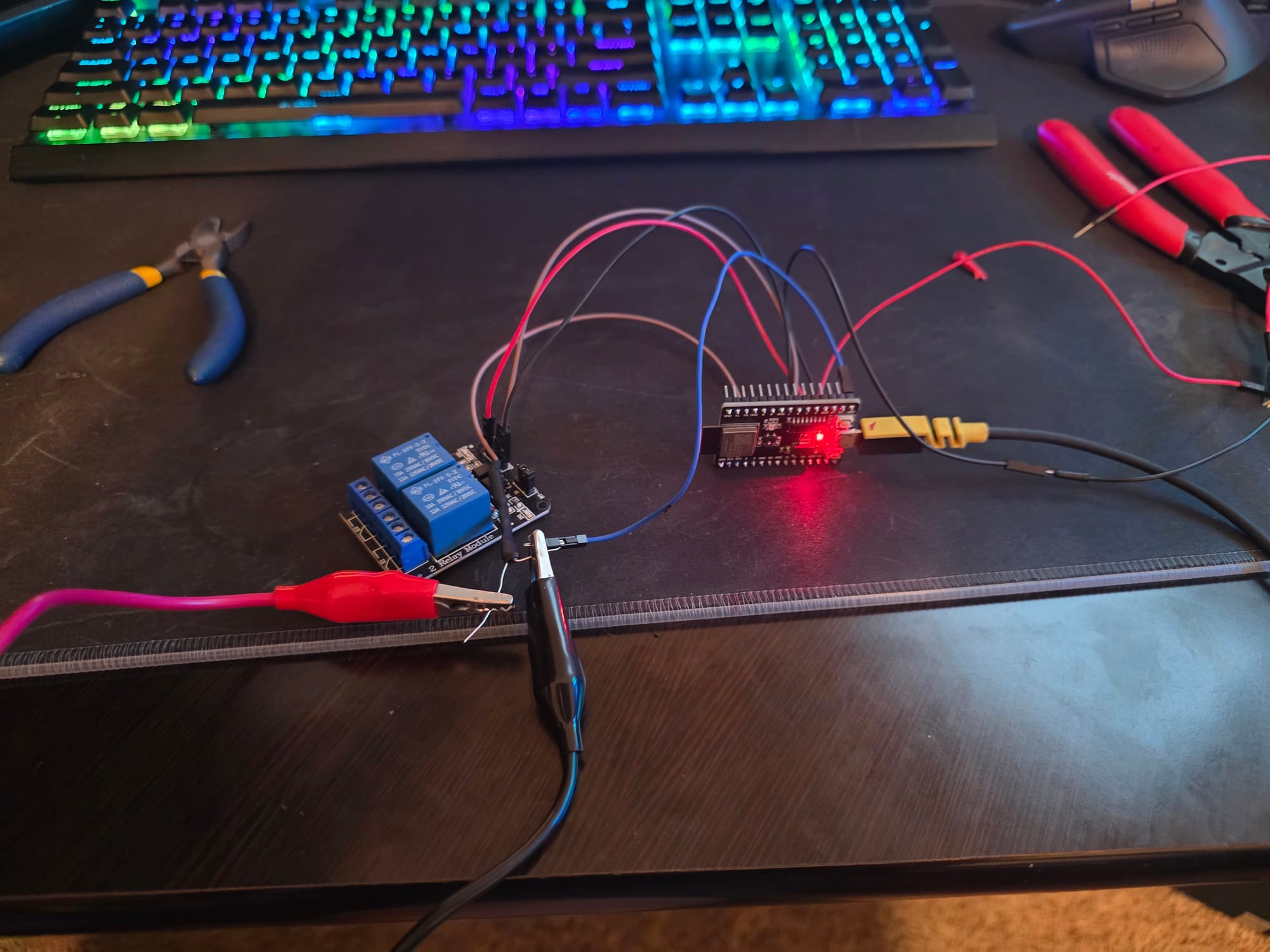
Originally, I thought about finding a breakout board I could purchase that had screw terminals, however, I couldn't find one that was in the right size for my specific model of development board. It also would mean that it would still be a mess, just not an insecure mess. I also would have to find ways to mount small components, like my voltage regulator and resistors.
That is when I realized, I should make a custom PCB! It would let me connect the small pieces directly to the board and would accommodate any features I wanted to add. A PCB would also allow me to make a 3D printed case much easier and include ports so that the main components could be easily disconnected, unlike a breakout board solution.
The Software
I searched across the internet and found many options for PCB creation software, but I landed on LibrePCB. It is open source, supports Linux, and is not too hard to use. That being said, it didn't run on Hyprland (my preferred Linux window manager) on my first try, so I used KDE Plasma during my PCB development, where it worked flawlessly.
When I first opened up the program, I was prompted to install libraries for components. I installed the default libraries, but I would now recommend installing every library, as I found a distinct lack of parts in the default libraries. This issue continued even after I installed all the other libraries, so I researched how to import other libraries.
Getting Your Parts in the Software
I was expecting for my research to find a library with more parts that I could simply install, however, I came across something even better. My research led me to DigiKey's unique EDA/CAD model downloads for each part they have. This lets you find the part that you want, and then import it directly into the software yourself and have it automatically place pads and holes where they need to be.
Modes of the Software
There are 2 different parts of the software that boards are developed in, the schematic and the board. The schematic is where you define what parts connect to what other parts. The position of these parts does not change their position on the board. The board is where you place the parts defined in the schematic and create the traces to connect each part to where it needs to be, which is conveniently shown with a yellow line that shows which part needs to be connected to which other part according to the schematic.
Making the Board
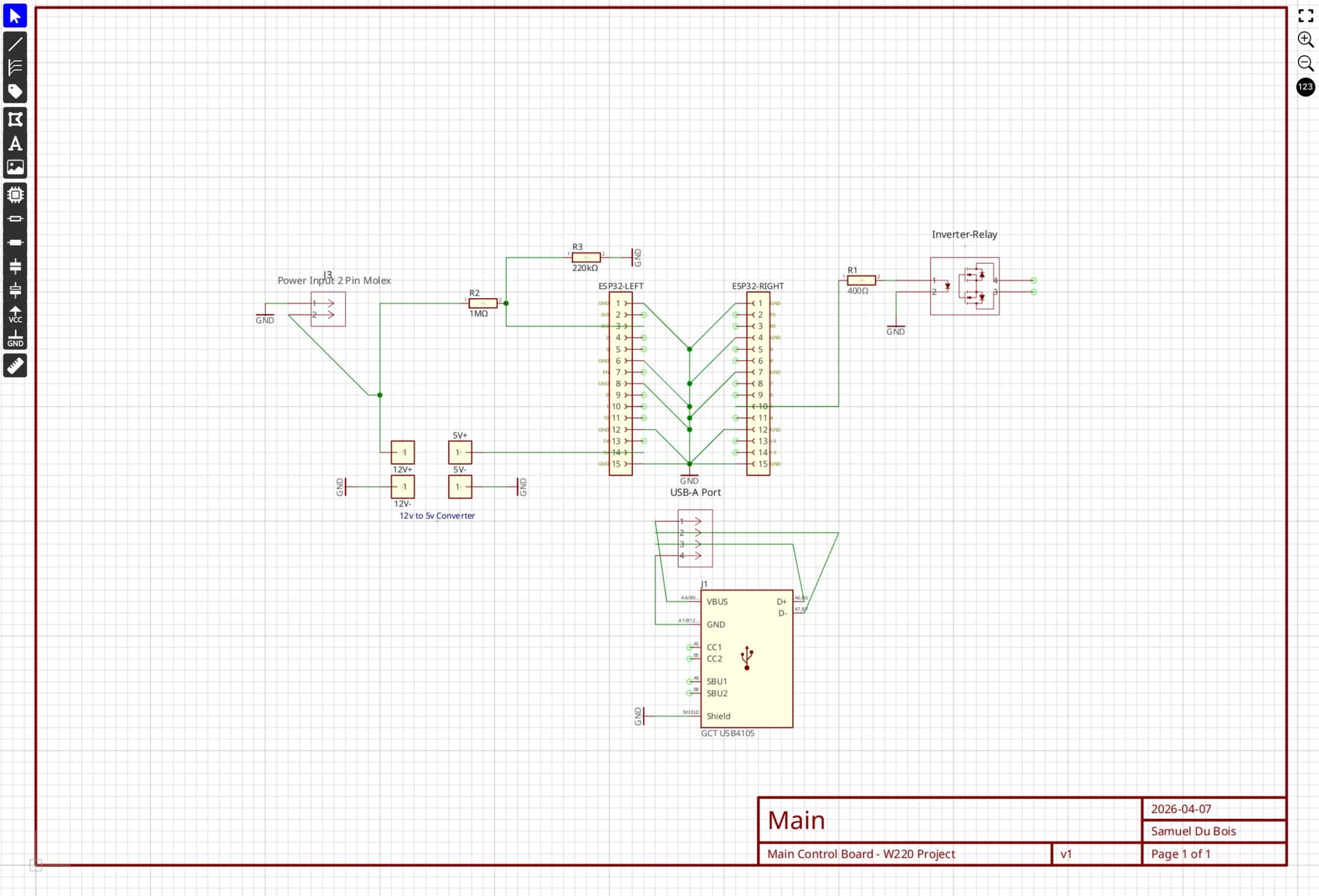
After I had figured out the software, I got to work building my board. At the center, I placed 2 1x15 female pin headers. These would let me slot in my ESP32 development board to the circuit board securely and still maintain the ability for it to be easily replaced in case of failure.
With the main socket out of the way, I started placing different supporting components on the board. After importing a 2 pin Molex connector, I wired it to supply the 12v power to the board from the car. I then connected that line to both the 5v voltage regulator and the voltage divider circuit that measures the battery voltage through an ADC pin on the ESP32.
After the 12v power was taken care of, I placed female pin headers on the board to connect my 5v regulator to. The output of this regulator was then wired up to the 5v rail on the ESP32 dev board.
Realizing that my dev board has a Micro-USB port for connection to a computer, I worked on passing it through to the edge of the mainboard. I placed a female USB-A port on the board, which was connected to a USB-C port on the edge of the board. The idea is that a small USB cable will connect the ESP32 to the USB-A port, which will connect to the USB-C port on the edge, where it will be accessible while it is installed.
I also discovered that using a custom circuit board allows you to use parts that usually wouldn't be widely available in a dev-board form, like a Texas Instruments ISOM8600DFGR, which is a solid state relay that makes much more sense to use as a replacement for my inverter's built-in switch than a large mechanical relay. It uses less power and can be put directly on the board, which makes it simpler to integrate with the ESP32.
Drawing the Traces
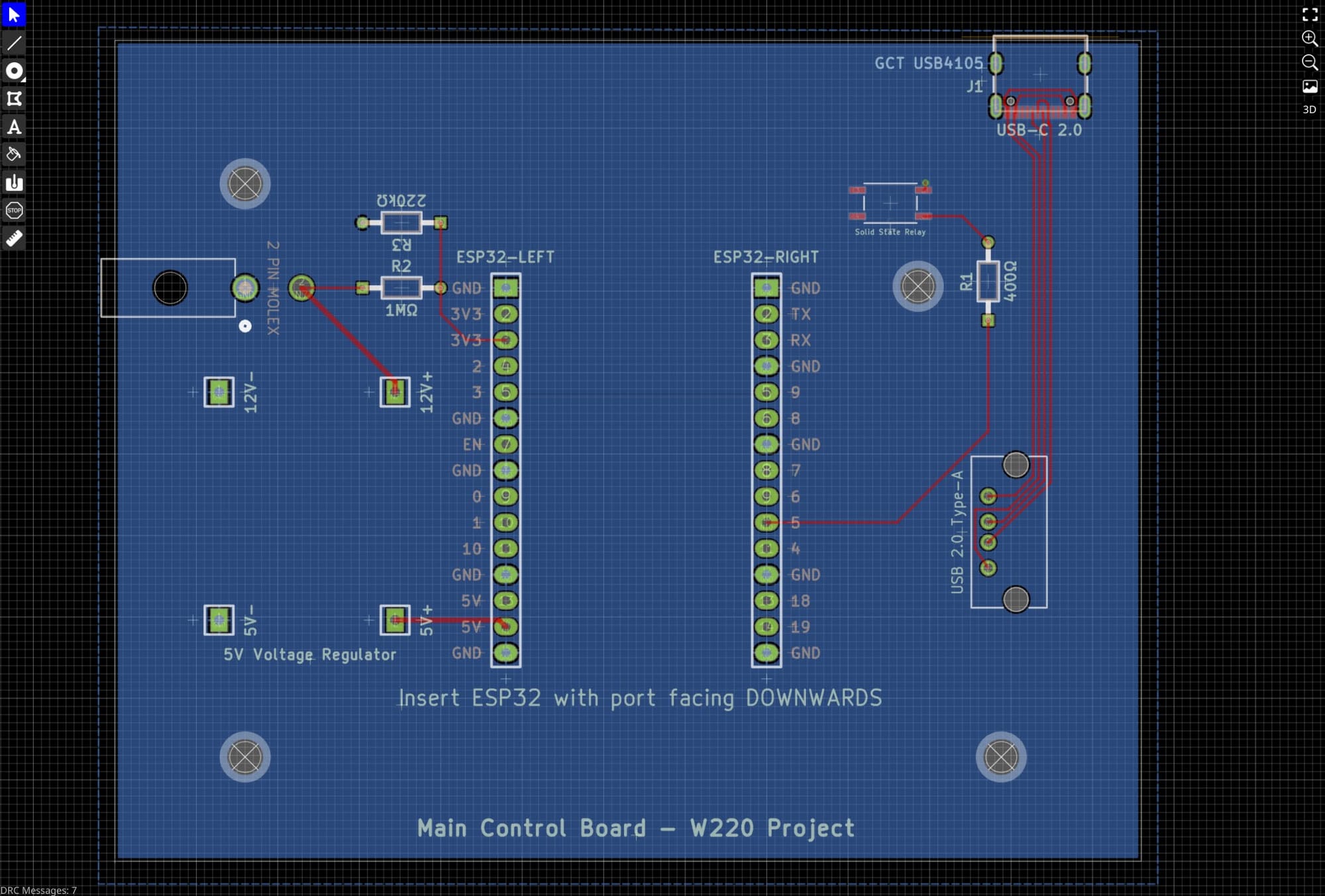
I then had to draw the traces between the different components. The internet told me that I shouldn't use 90 degree turns and that I would need to change the width of the traces depending on how much current they were delivering. I gave my power traces a greater width compared to my data traces.
I also ran into issues trying to route certain traces on a single layer PCB. Realizing that I have to be smart in how I place things on the board, I made adjustments to make sure that I could route all of my traces without overlapping them, however, I then realized that I didn't need to limit myself to a single-layer board because dual-layer boards are similar in price.
After switching to a dual layer PCB, I learned that I should make the bottom layer a ground layer by making the entire bottom of the PCB a single sheet of copper. I discovered in my research that a ground layer is better because it reduces interference, which is important in a noisy car electrical system, and also acts as a heat sink for any heat generating components. It also makes it easier to route ground traces, as they are automatically connected to the bottom of the board if you tell the program to connect a pin to ground in the schematic mode.
Adding the Connectors
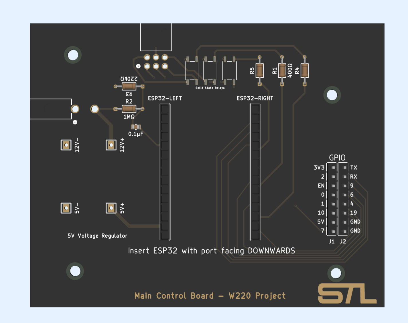
I decided to use a 6-pin Molex Nano-fit connector for my solid-state relays (yes, plural). I used it because of its small size and locking connector, although it was very difficult to decide between all the different options. The 4 extra pins were used for the extra 2 relays that I decided to add for expandability in the future.
For the power connector, I decided to use a bigger 2-pin Molex Mini-fit Jr. for the same reasons as the solid-state relay connector.
It was at this stage that I realized that the USB-C port wasn't as simple as I thought it would be to implement because of capacitors that the USB spec requires on certain pins. Instead of adding these capacitors, I decided that the USB system was taking up too much space and replaced it with something even better.
GPIO Pins!
Yes, I added GPIO pins. More accurately, I passed through the unused GPIO pins from the ESP32 dev board I was using because I wanted to be able to test adding features to the board without getting a new board manufactured and shipped.
I used 2 side by side 1x8 male pin headers to make up the GPIO pins and then routed them to the corresponding pins (which required quite using the lower layer quite a bit) and labeled them on the silkscreen.
Manufacturing
Now that I was done with the board, I had to figure out how to get it manufactured.
I had heard of PCBWay before on various YouTube channels before and decided to use them because of their low prices ($5 for 5 boards). I went through the configurator, making sure to select matte black for the soldermask. My design was then sent to PCBWay to be verified, and it was ready to order in about 5 minutes.
What's a Tariff?
When I got to the delivery portion, I was perplexed. I knew that I would have to pay tariffs, but I didn't know what shipping option to select to not have to pay too much in tariffs.
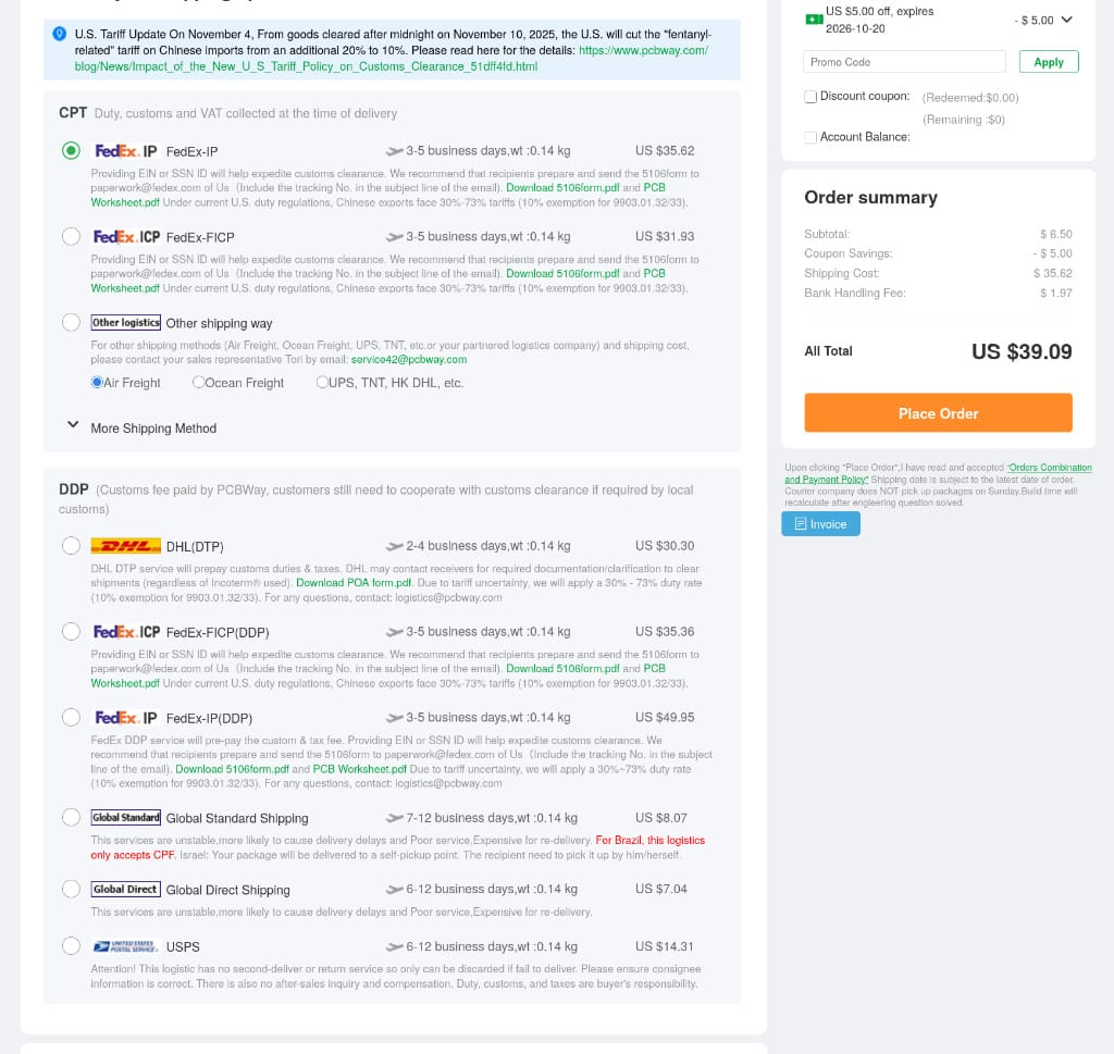
There were 2 categories, CPT and DDP.
CPT was the option where all customs and duties were collected at time of delivery without any sort of estimate for how much they would be, so I didn't want to choose that.
DDP (Custom fee paid by PCBWay) is where it gets interesting though, because there were different (strange) options. (Yes, the grammar mistakes are part of the quotes)
- DHL (DTP) $30.30 - "Prepays customs duties & taxes" and also "due to+ tariff uncertainty, we will apply a 30% - 73% duty rate (10% exemption for 9903.01.32/33)"
- FedEx (DDP) $35.36 - Wants me to provide an EIN or SSN to expedite customs clearance. Says Chinese exports face 30% - 73% tariffs but doesn't state if they are paying them, but I assume they are because they are in the DDP section where PCBWay pays customs fees.
- Global Direct Shipping $8.07 - "This services are unstable,more likely to cause delivery delays and Poor service,Expensive for re-delivery." Says nothing about tariffs at all, which is concerning, but it is in the DDP category where they pay "customs fee".
- USPS $14.31 - Says they do not pay duty, customs, or taxes even though it is in the DDP category.
What did I choose? I chose "Global Direct Shipping" and still don't know if it was a good choice or if I am going to get hit with a $500 customs fee (or if it will even make it here), but it was cheap and I think it will be okay because the boards themselves cost $5 for 5 boards.
Pray for my delivery that is "unstable,more likely to cause delivery delays and Poor service,Expensive for re-delivery" to actually arrive!