
Power Automation? - ESP32 Integration - W220 Project
Now that I had cleaned up the physical power situation in my car, it was time to make it work automatically. I had many different ways that I could do this, but I settled on using an ESP32 to control the switch on my inverter because it let me program exactly how it would work.
So how did I program it to work?
I created a plan and brainstormed exactly how I wanted the system to operate, saving power when the car is off, but enabling the inverter when either the car is on or the solar panels are providing sufficient power. I could have done this by running a wire from a switched fuse that would turn the inverter on when the car's ignition was in the on position, however I saw multiple disadvantages to that approach.
- It could turn on the inverter when the engine is off, but the ignition is in the on position, which could significantly drain the battery if a large draw is connected. (This is why the engine must be running for many OEM inverter implementations)
- It would not automatically work with the solar panel system without a separate integration.
- It would require running a wire from a switched fuse under the hood all the way back to the trunk.
After some thinking, I came to the conclusion that the best trigger for turning on the inverter would be reading a voltage measurement from the 12v system. If the voltage represented the engine and solar being disabled, it would shut off.
Electrical Circut
I decided to use 2 resistors to lower the voltage going into the ESP32's ADC pin, which outputs a value between 0 and 4096. I used a 1MΩ as the first resistor, with a 220kΩ resistor for the second resistor. In between these resistors is where the ESP32 ADC pin was connected. The 1MΩ resistor was connected to the 12v source and the the 220kΩ resistor connected to ground.
This means that it would step down the 12v input to 2.4v, which gives plenty of headroom before the pin would overvolt.
I then decided to connect a relay to the ESP32 to control the switch on the inverter programatically.
The Code
To convert the ADC pin to 3.3v, I divided the value by 4095 and multiplied by 3.3. I then ran a linear regression comparing the read input (x) to the actual input (y) to verify the conversion factor of 5.
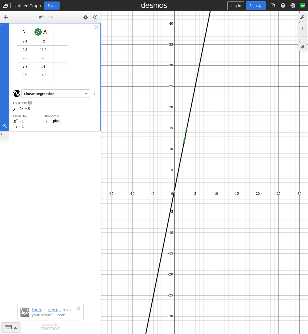
To implement this in the code I read the ADC value, converted it to 3.3v, and then multiplied by 5 to get the real voltage.
To control the ESP32 automatically, I coded a simple else if statement that turns off the relay at the INVERTER_OFF_THRESHOLD, turns it on at the INVERTER_ON_THRESHOLD, and prevents it from being turned on by the app at the INVERTER_EMERGENCY_THRESHOLD (unless debug mode is enabled).
All the code for this can be found at github.com/sometingrandom-MC/w220-project-esp32.